
I. Basic Project Introduction
1.1 Geographical Conditions
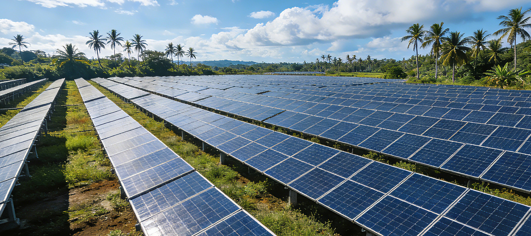
The Philippines is located in the tropics, with long hours of sunshine throughout the year and high solar radiation intensity. It is an ideal area for the development of photovoltaic power, with an average annual sunshine duration generally exceeding 1,600 hours. Sufficient and stable sunlight not only ensures the continuous and efficient power generation of photovoltaic projects, but also reduces the cost of power generation.
1.2 Introduction to Microgrids
A microgrid refers to a power generation and distribution system formed by organizing small-scale power generation units (distributed power sources), energy storage devices and local loads that are scattered within a certain area. It can operate in parallel with the conventional power grid or independently. Off-grid microgrids specifically refer to microgrids with independent operation capabilities. This project adopts off-grid microgrids.
The core secondary system of an off-grid microgrid is the energy management system. EMS(Energy Management System)plays a key role in off-grid microgrids, providing comprehensive and diverse off-grid microgrid management functions. Through real-time monitoring, control and dispatching of microgrids, EMS(Energy Management System)can effectively enhance the safety, efficiency and economy of microgrid operation.
II. Construction Plan
2.1 Construction Scale
The enterprise load is approximately 2MW, and it is expected to meet the working electricity demand for 8 to 10 hours. There are 20 mu of open land available for the construction of photovoltaic systems. With an annual sunshine duration of 1,600 hours, the theoretical average daily effective irradiation time of photovoltaic power is approximately 4.38 hours, and it is necessary to be equipped with energy storage and diesel generators.
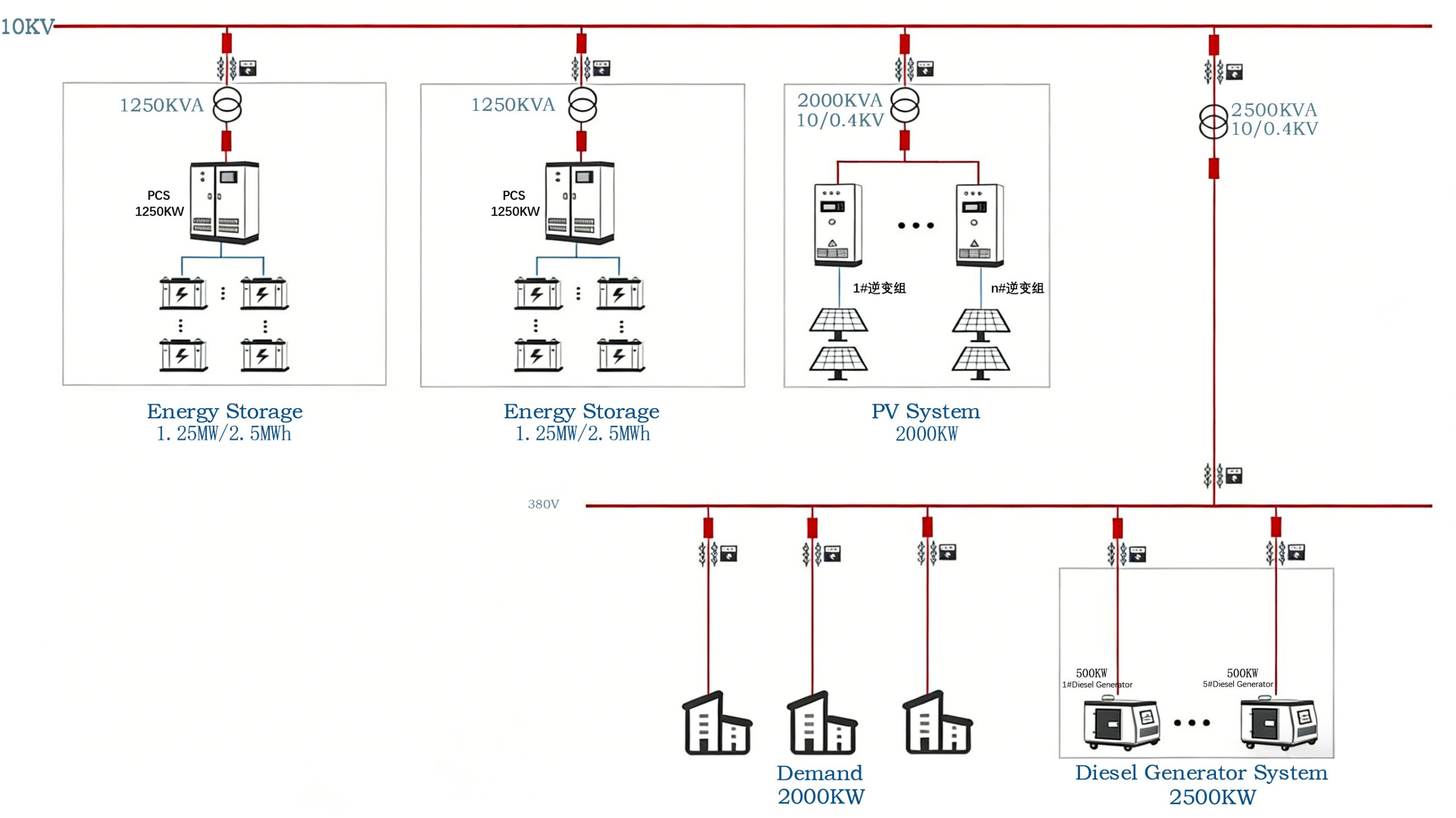
A microgrid can be formed by building a 2MW photovoltaic system, a 2.5MW/5MWh energy storage system and a 2.5MW diesel generator. The above construction plan takes into account that it can also ensure the normal operation of the mine equipment in rainy and cloudy weather. The specific construction scale is subject to the actual on-site situation.
The operation of the entire power grid is supported by energy storage as the voltage source, and the energy storage system operates in V/F mode. Photovoltaic and other current sources supply power to the load and charge the energy storage system, while diesel generators serve as backup power sources. In this mode, the energy storage system plays a role in stabilizing the grid voltage. It regulates the grid voltage and frequency through the charging and discharging of energy storage, ensuring the stability and reliability of the system.
2.2 Microgrid Operation Strategy
2.2.1 Operation Strategy for Energy Storage Microgrids
The energy storage VF mode serves as the voltage source, while the diesel generator and photovoltaic PQ modes act as the current source. Among them, the energy storage is the main power supply, and the diesel generator is the backup power supply.
The rated power of energy storage should be greater than the average power of the peak load. While photovoltaic power is consumed locally, the surplus electricity is used for energy storage and charging. When photovoltaic power generation is insufficient or the energy storage power is inadequate, diesel power generation is activated to replenish the power for energy storage.
2.2.2 Energy Management
♦ Power coordinated control
Photovoltaic output control: When photovoltaic power generation is sufficient, priority should be given to using photovoltaic power to supply local loads. If there is still a surplus in photovoltaic power generation and the SOC of energy storage has not reached the upper limit, the power of photovoltaic power generation can be released to charge the energy storage.
When the SOC of the energy storage reaches the specified upper limit, the power of photovoltaic power generation should be restricted to prevent overcharging of the energy storage.
Output control of diesel generator set: After starting the diesel generator for power replenishment, set the output power of the diesel generator to the optimal load operation power.
♦ Power balance control
The energy storage system operates in VF mode and can automatically adjust the output power to achieve system power balance.
When the power of photovoltaic power generation suddenly drops or the power consumption of the load suddenly increases, resulting in insufficient system power, the energy storage system can provide additional electricity to maintain the stable operation of the system. On the contrary, when there is an excess of photovoltaic power generation or a sudden drop in load power, the energy storage system can adjust the output power to store the excess electrical energy.
Meanwhile, when EMS detects load fluctuations, it will adjust the power generation of the photovoltaic system in real time, further enhancing the safety and stability of the system.
♦ Energy storage SOC management
During the operation of the system, there may be a situation of power shortage in the energy storage, and it is necessary to recharge it.
When the SOC of the energy storage is lower than the lower limit value, the diesel generator is started in PQ mode to enter the energy storage charging state. On the contrary, when the SOC of the energy storage reaches a fixed value, the energy storage charging state is exited. Users can dynamically adjust the management strategy of energy storage SOC based on the actual operation conditions or the trends of photovoltaic and load forecast curves.
♦ Diesel generator start-stop strategy
When the system has multiple diesel generators, the switching strategy follows the following principles:
The number of units started and stopped is based on the ratio of the load power to the rated power of the diesel generator.
It is stipulated that the optimal operating load of diesel generators should be between 30% and 80% of the rated load. This not only ensures that diesel generators have sufficient output space to respond to the microgrid but also avoids problems such as increased exhaust, carbon deposits, and component wear caused by long-term low-load use of diesel generators.
♦ Load switching control
Three-level load management. Determine whether the SOC of the energy storage is lower than the lower limit value of a certain grade, and accordingly cut off the load of that grade to ensure the long-term power supply of important loads. If the energy storage SOC returns to the upper limit value, the power supply to the corresponding grade load will be restored to realize the function of load classification management.
2.2.3 Safety Protection
♦ Active energy storage protection
The microgrid control sets the active protection threshold for the energy storage system. When the threshold is triggered, the microgrid issues a shutdown instruction. Take the protection of energy storage SOC as an example. In the case of continuous rainy days, when the energy storage SOC reaches the specified lower limit value, the energy storage system is controlled to shut down to prevent the energy storage battery from being drained.
When the photovoltaic power is out of control, the photovoltaic system continuously charges the energy storage. When the SOC of the energy storage reaches the specified upper limit, the energy storage system is shut down to prevent overcharging of the energy storage battery. Others also include temperature protection, temperature difference protection, individual voltage protection, individual voltage difference protection, insulation protection, etc.
♦ Fire linkage
The energy management system can be connected to the fire protection system to identify and respond to fire signals, disconnect the corresponding switches, and prevent the situation from worsening.
III. Main Equipment
| NO. | Device Name | Remarks |
| 1 | Solar Modules | |
| 2 | Solar Mounting Bracket | |
| 3 | Combiner Box | |
| 4 | PV Inverter | |
| 5 | PV Grid Connection Cabine | |
| 6 | Energy Storage Battery Compartment | |
| 7 | Power Conversion System | |
| 8 | Step-up Transformer | |
| 9 | Energy Storage Grid Connection Cabinet | |
| 10 | Diesel generator set | |
| 11 | Diesel Generator Grid Connection Cabinet | |
| 12 | Secondary Control Cabinet | |
| 13 | Integrated Energy Management System Control Cabinet |